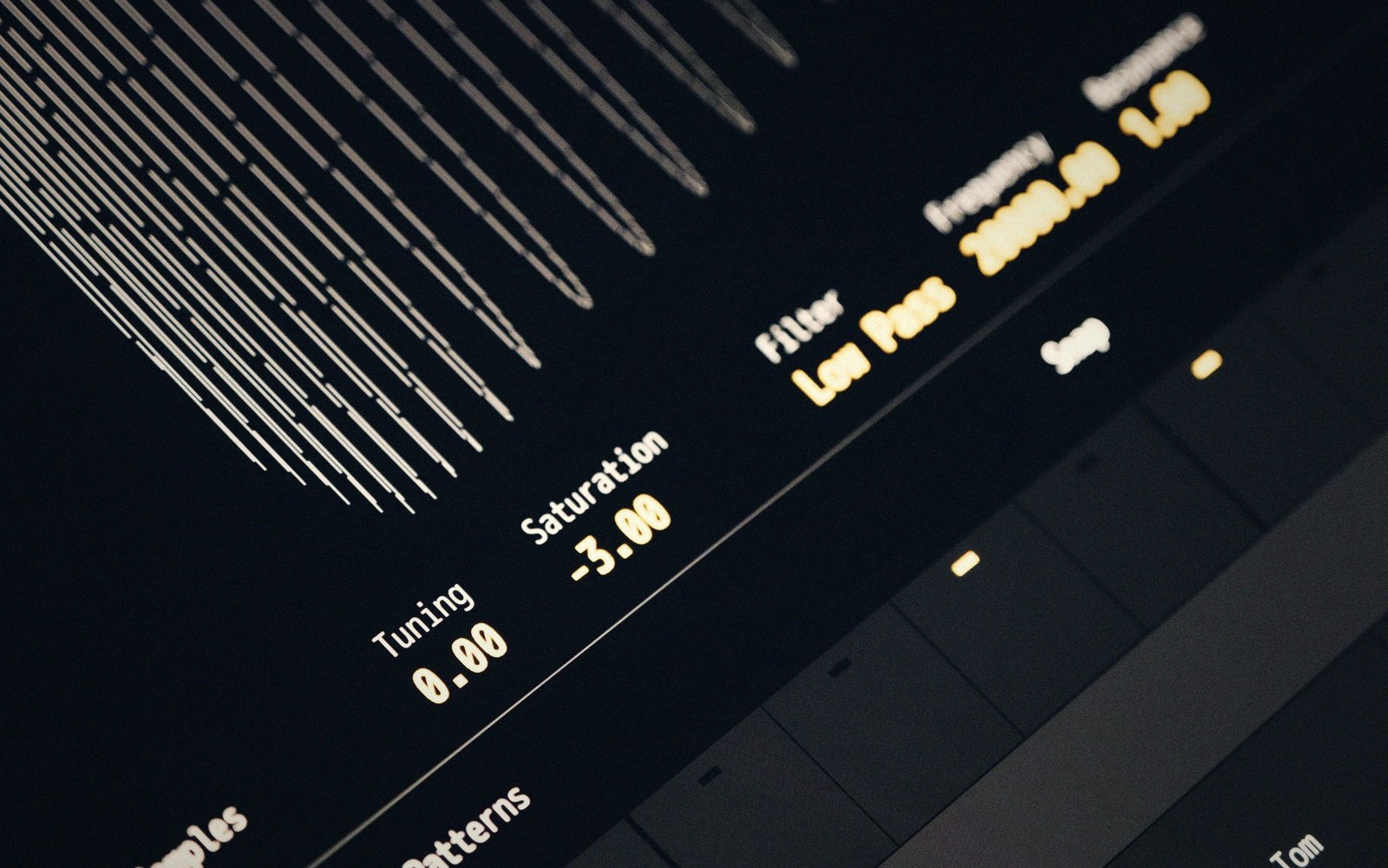
A filter is not a tone control — it is a decision about harmonics
A sine wave has one frequency. Everything else — every buzzing, biting, warm, hollow, or airy quality you hear in a synthesiser patch — is the result of harmonics stacked above a fundamental. A sawtooth wave contains all harmonics, falling in amplitude as frequency rises. A square wave contains only odd harmonics. A pulse wave shifts that ratio as the duty cycle changes. The filter's job, in every case, is to choose which of those harmonics survive at the output and which do not. That is not metaphor; it is the literal description of what the circuit does.
The word "tone" is a trap. It suggests an overall coloration, the way you might warm up a recording with an EQ shelf. What a filter actually does is closer to surgery: it acts on individual frequency components of a waveform, passing some and attenuating others, and the result is a different waveform — one whose harmonic series has been reshaped. To understand what you are doing when you turn a cutoff knob, you have to think about harmonic content first and timbre second.
What each configuration removes — and what it keeps
Low-pass. The most common filter type in subtractive synthesis. A low-pass filter passes frequencies below the cutoff point and attenuates everything above it. In spectral terms: the fundamental and the lower harmonics survive, while the upper partials are progressively removed. A sawtooth wave processed through a low-pass filter with a low cutoff frequency becomes a shape that is closer to a sine — not because the filter generates a sine, but because the harmonics that distinguished the sawtooth from a sine have been taken away. The slope of that attenuation — typically 12 dB or 24 dB per octave — determines how abruptly the upper harmonics disappear. A 24 dB per octave slope removes a harmonic two octaves above cutoff by around 48 dB; it is, in practice, nearly gone. A 12 dB slope is gentler, and harmonics above cutoff trail off more gradually, which is why 12 dB filters are often described as more open-sounding: the attenuation is real but the upper harmonics are not silenced, just turned down.
High-pass. The inverse operation. Frequencies above the cutoff survive; those below are attenuated. In harmonic terms, a high-pass filter removes the fundamental and the low partials while leaving the upper harmonics intact. Run a square wave through a steep high-pass filter and the body of the note disappears — the result contains mostly the fast transient energy and upper odd harmonics. High-pass filters are often used in modular practice to thin a signal rather than to reshape it dramatically, because removing the fundamental of a rich waveform leaves something that can feel thin and buzzy before it becomes musically useful. A moderate high-pass cutoff, however, can remove mud without gutting a patch — which is why high-pass filters at moderate settings are a tracking tool as much as a sound-design one.
Band-pass. A band-pass filter combines a high-pass response and a low-pass response, passing only a band of frequencies around the cutoff point and attenuating both what is above and what is below. The harmonic content that survives is a slice of the original spectrum. The width of that slice — the bandwidth, or conversely the Q — determines how selective the filter is. A high Q setting makes the band narrow: only harmonics close to the cutoff frequency pass, and the resonance peak becomes sharper. Driven into self-oscillation, a high-Q band-pass filter behaves like a sine-wave oscillator, because at that point the resonant peak itself is the signal. In modular use, a slowly swept band-pass filter picks individual harmonics out of a complex waveform one at a time, which is why the wah-wah effect is formally a band-pass sweep — it is revealing one harmonic at a time as the cutoff moves through the spectrum.
Notch. Also called a band-reject or band-stop filter. The notch is the complement of the band-pass: it removes a narrow band of frequencies and passes everything outside that band. Harmonically, a notch filter subtracts a specific partial from the waveform and leaves the rest intact. The effect of moving a notch through a complex waveform is subtler than a band-pass sweep — instead of one harmonic becoming prominent, one harmonic at a time disappears. At high Q settings, the notch can be made very narrow, surgical enough to remove a single partial with minimal effect on adjacent frequencies. In practice, a notch at audio rate can cancel specific spectral content; a notch swept slowly by an LFO creates the phasing characteristic of a phaser effect, because phasing is a series of notches moving through the frequency spectrum together.