CYNDUSTRIES The signal path, taken slowly.

Home / Signal & Path

One Fluid, Three Names

Pull a cable out of an oscillator's audio output and plug it into a CV input. The oscillator that was playing a pitch is now sweeping a filter or bending another oscillator's frequency. The cable didn't change. The voltage didn't fundamentally change. What changed was context — how fast the signal moves and what range of values it occupies, and whether the receiving module cares about those values in terms of pitch, cutoff, or on/off logic.

This is the core fact modular synthesis is built on: every signal in the system, without exception, is a voltage varying over time. Audio is voltage moving fast enough — typically in the range of twenty to twenty thousand times per second — to be heard as sound when converted to air pressure by a speaker. A low-frequency oscillator putting out a slow triangle wave is voltage moving at a fraction of a cycle per second, leisurely enough to be felt as a rhythmic swell rather than a tone. A gate signal, which tells a module when to open or activate, is voltage switching between a low state and a high state — in Eurorack, typically zero volts and five volts. Different names, different jobs, same substrate.

Understanding this matters practically, not philosophically. When a filter behaves strangely, or a module doesn't respond to a patch cable the way you expected, the question to ask is always: what voltage is actually arriving at that input, and what does this module expect? Everything else is interpretation of that question.
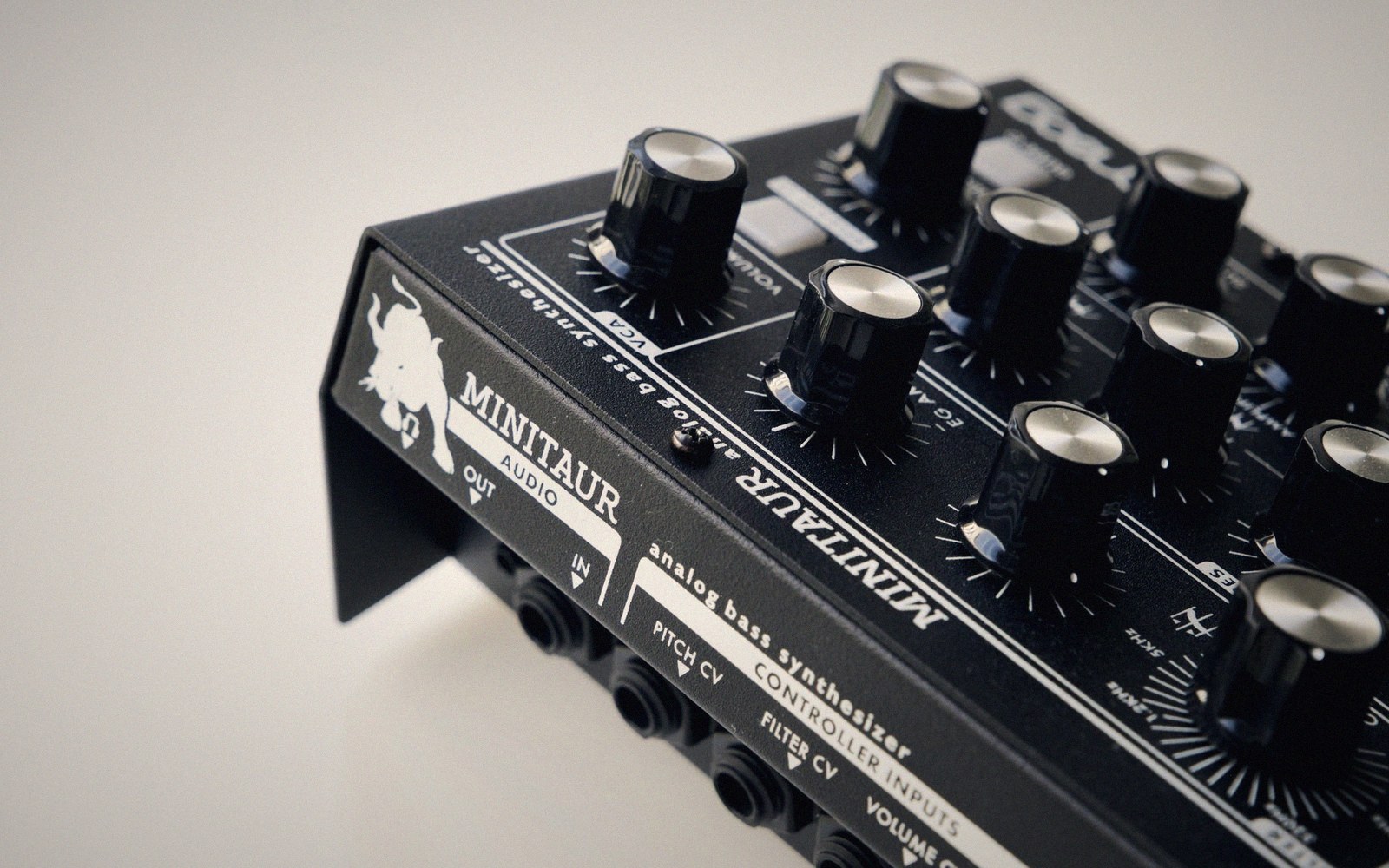
Close-up of a Moog Minitaur analog bass synthesizer with black knobs and input jacks
Audio, modulation, and gates are the same substance doing different jobs — once you see that, the patch opens up. — Photo: Egor Komarov / Pexels

Rates and Scales

The most useful way to map the territory is by thinking in two dimensions: rate (how quickly the voltage changes) and scale (what range it sweeps through).

Audio signals move fast. They also tend to be bipolar — swinging both above and below zero volts — and their peak amplitudes in Eurorack are typically in the range of five to ten volts peak-to-peak, though this varies between manufacturers and modules. Because they move so fast, a module's circuitry must respond on that timescale; audio path components are sized accordingly.

Control voltages — CV — are the slower signals. They move at rates from sub-audio down to near-static. An envelope generator produces a voltage contour that rises and falls over the span of a note; it might take seconds to complete a full cycle. An LFO might cycle once every few seconds, or slower. Pitch control uses the 1V/oct standard, where every one-volt increase corresponds to exactly one octave of pitch change — a beautifully simple convention that makes melodic control precise and predictable.

Gates occupy a third region: they're not really about contour or rate in the audio sense, but about discrete state. High or low. Open or closed. The voltage is binary in intention even if the transitions aren't instantaneous in the physics. A gate holds high for as long as a key is depressed or a sequencer step is active; a trigger is a brief pulse, often just a few milliseconds. The distinction matters — some inputs want a sustained gate, others only need the leading edge. Gates hold while triggers fire, and a circuit designed for one may respond incorrectly to the other.

Close-up of a Moog Minitaur analog bass synthesizer with black knobs and input jacks
Audio, modulation, and gates are the same substance doing different jobs — once you see that, the patch opens up. — Photo: Egor Komarov / Pexels

What the Format Tolerates

None of this is entirely open — every format defines guardrails. In Eurorack, the power rails run at plus and minus twelve volts, and a signal that exceeds roughly plus or minus twelve volts risks damage, either to the output stage producing it or the input receiving it. Most modules include protection of some kind, but that protection is not unlimited. Modular systems are less buffered than fixed-architecture instruments; the path between modules is often a direct connection, which means an out-of-range voltage doesn't just fail gracefully — it hits something directly.

The practical upshot: when you patch something unexpected — an audio signal into a CV input, or a gate into an audio path — ask whether the voltage levels are compatible before you assume the patch will work. An audio-rate signal into a slow CV input might overload the slew circuitry. A gate into an audio path might introduce clicks. These aren't catastrophic errors most of the time, but they produce specific, diagnosable effects, and understanding that voltage is the shared language is what makes those effects readable rather than mysterious.

Once you've absorbed this frame — voltage at different rates, different scales, interpreted differently by different circuits — every module you encounter becomes legible. The knobs are setting voltage ranges. The inputs are voltage expectations. The outputs are voltage commitments. The patch cable is translation, one circuit's offer to another.

The two-axis map

  • Rate — how many times per second the voltage changes; separates audio from modulation from static CV
  • Scale — the voltage range swept; separates Eurorack's ±12 V rail headroom from typical signal amplitudes of ±5 V

Follow a cable