CYNDUSTRIES The signal path, taken slowly.

Home / Repair & Calibration

Orient Before You Probe

The first thing a PCB tells you is not what each component does — it tells you which direction the signal travels. Power enters from the header, usually a 10- or 16-pin IDC connector sitting near one edge. The decoupling capacitors — small ceramics or electrolytics clustered tightly around ICs — almost always sit right at the power pins. Find those caps and you have found your power rails. From there, the signal chain tends to run left-to-right or bottom-to-top in the majority of commercial Eurorack layouts, though this is convention, not rule.

Reference designators are your next anchor. The silkscreen on any competent board will label components with a letter prefix and a number: R for resistors, C for capacitors, D for diodes, Q for transistors, U or IC for integrated circuits, RV for potentiometers. These designators are not random — designers usually number them in rough signal-flow order. U1 is frequently the first active stage after the input; U2 or U3 often handles the bulk of signal processing. When the numbering breaks sequence, it usually means a sub-circuit was added late or the board was revised.
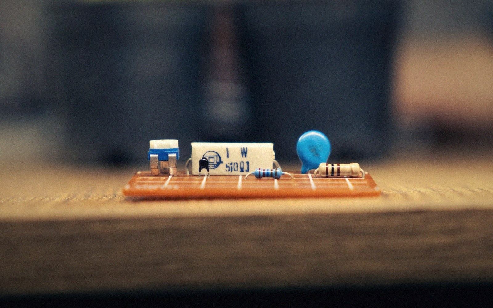
Resistors, a capacitor and a blue diode mounted on a small circuit board
You have the board in front of you. Here is how to start making sense of it. — Photo: Abolfazl Pahlavan / Pexels

Topology Patterns That Identify Themselves

Once you can see the ICs, you can read the topology. A dual op-amp (an 8-pin DIP or SO-8 package) with its output tied directly to the inverting input is almost certainly a unity-gain buffer. Add a resistor from a signal source to the inverting input and a larger one in the feedback path and you have an inverting amplifier; the gain is simply the ratio of those two resistors. A quad op-amp with its outputs tied directly back to its inverting inputs is a buffer bank — common at the input stage of mixers and VCAs.

Transistor pairs deserve attention. A matched pair — two BJTs or JFETs in close proximity, often thermally coupled with a blob of compound or physically touching — is almost always a differential pair, which appears in VCA cores, exponential converters, and the 1V/oct scaling circuit that every pitch-tracking oscillator depends on. The exponential converter, in particular, is why many oscillators have a trimmer nearby: tempco compensation for exactly that transistor pair.

A quad of diodes arranged in a diamond around a transformer or a pair of output rails is a bridge rectifier — relevant only if you are looking at a power section. A single diode across a relay coil is a flyback suppressor; a zener diode from an input to ground or a rail is a clamp. These patterns are universal and once you recognise them you can read almost any analog board at a glance.

Resistors, a capacitor and a blue diode mounted on a small circuit board
You have the board in front of you. Here is how to start making sense of it. — Photo: Abolfazl Pahlavan / Pexels

What You Cannot Read From the Silkscreen

Certain things are genuinely opaque without the schematic. IC pin functions vary by part number, and a plain "U3" marking tells you nothing until you read the chip's own markings and look up the datasheet for that specific device. CMOS logic chips, VCAs, and dedicated synth chips like the CEM or SSM families all have non-obvious internal topologies. The chip marking is almost always visible — a five- or six-character string on top of the package — and that string, not the PCB label, is what you search for.

Trimmers require the same caution. You can see that a trimmer is in a feedback path or on a rail, but whether it sets offset, scale, or frequency needs the schematic to confirm. What the trimmers are actually for is a question the board alone can only partially answer. Touch nothing until you know what adjusting it changes — and when in doubt, photograph the board's current state before you probe anything that moves.

Topology quick-reference

  • Unity-gain buffer — op-amp with output tied to inverting input
  • Inverting amplifier — gain set by resistor ratio
  • Differential / matched transistor pair — VCA cores, expo converters
  • Bridge rectifier diamond — found in power sections only
  • Flyback suppressor diode — across relay coils
  • Zener clamp — series with inputs

Follow a cable